マイクロ流体チップ内の電気浸透流の測定
非接触伝導度検出器を使ってマイクロ流体チップ内のチャネルに流れる電流をモニターし、 電気浸透流 ( EOF: electro-osmotic flow ) を測定しました。
Contents
はじめに
PDMS (ポリジメシルシロキサン) マイクロ流体チップ内の電気浸透流を、静電結合型の非接触電度計 (C4D: capacitively-coupled contactless conductivity)を使ってチャネルに流れる電流をモニターすることによって測定しました。測定データは eDAQのPowerChrom で記録し解析しました。ここで報告する方法は、従来のフューズトシリカチューブを使ったキャピラリー電気泳動を含め、様々なタイプのキャピラリー電気泳動測定にも応用できます。
この独創的な研究は Henry at the Department of Chemical and Biological Engineering, Colorado State University. qian.guan@colostate.edu の Qian Guan 及び Dr. Charles S 等によって実施されたものです。
使用した装置
- ER225 C4D データシステム
- ET225 マイクロチップ用プラットフォーム
- コンピュータ PowerChrom ソフトウェア
- バックグランド電解液 (BGE): 20 mM 及び 18 mM ホウ酸(pH 9.20)、ホウ酸以外でもイオン強度が異なる二種類の溶液であれば構いません。
- Poly(dimethylsiloxane) (PDMS) マイクロ流体チップ-リザーバ2ケにつなぐことが可能な直線流路を有するもの
チャネル(流路)のサイズ: 長さ 4.75cm、幅 50μm、高さ 50μm
- 専用の高電圧シーケンサ (HVS)、ER230 高電圧シーケンサ
このアプリケーションでは ER280 PowerChrom システム、旧型の EA120 C4D アンプと ET121 プラットフォームを使いました。
測定条件
ここで紹介する測定データは、下記の測定条件で記録したものです:
- 高電圧: +881 V
- C4D 設定:
- 周波数 = 500 kHz
- アンプリチュード = 100 %
- ヘッドステージゲイン ON
測定のセットアップ
C4D アンプからの出力 K シグナルをPowerChrom ユニットの入力1に接続します。PowerChrom ユニットの入力2で電流をモニターします。この二つのシグナルを PowerChrom ソフトウェアで連続的に表示させて記録します。
Electro-osmotic Flow Measurement using the Current Monitoring Method
The current monitoring method for EOF measurements was described previously (Huang, X., Gordon, M. J., Zare, R. N., Anal. Chem. 1988, 60, 1837–1838). Briefly, the first reservoir and the channel are filled with 20 mM BGE and the second reservoir is filled with 18 mM BGE. Upon application of high positive voltage in the first reservoir, EOF causes the lower concentration electrolyte solution to gradually displace the higher concentration BGE in the channel, resulting in an increase in the electrical resistance of the channel. The change in separation current under a constant applied voltage difference is monitored. Once a constant current is obtained, the potential is reversed and the above procedure repeats.
The time required to reach a current plateau is used to calculate EOF based on Equation 1, where L is the length of the separation channel, V is the total applied voltage, and t is the time in seconds required to reach the new current plateau.
μEOF = L2/Vt Equation 1
Electro-osmotic Flow Measurement using the C4D
The microchip is set up for a close contact with the C4D microfluidic platform by spring screws. The desired detection point in the microchip channel is located at the center position between two detection electrodes on the surface of C4D microfluidic platform. The BGE loading and voltage control in this method is the same as that described in the current monitoring method and the two methods can be run at the same time.
It is generally recommend to use a microchip which has a bottom sheet with a thickness no higher than 0.5 mm, to obtain highly sensitive conductivity detection. Do not move or touch C4D microfluidic platform during experiments to avoid creating noise.
The time required to reach a sharp conductivity change from the beginning stable status is monitored using the C4D Amp. EOF is calculated based on Equation 2 where L’ is the distance between the reservoir where EOF starts flow and the detection point, and the other parameters are the same as those in Equation 1.
μEOF = L’L/Vt Equation 2
Results
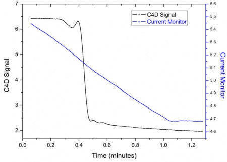
Figure 1 shows electropherograms for EOF measurements using both the current monitoring method (blue plot) and C4D (black plot).
The current monitoring method gives the average conductivity along the channel, as the channel is filled with the BGE of lower concentration. This produces a gradual decrease in the current monitor, until the whole channel is filled with the BGE of lower concentration, and a plateau is reached.
The C4D signal gives a conductivity measurement at a particular point along the channel, and thus there is a sudden decrease in conductivity, when the BGE of lower concentration reaches the position of the C4D electrodes.
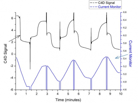
Figure 2 shows the electropherogram of all the data, where the voltage is applied first in one direction, and then is reversed to make the EOF travel in the opposite direction along the chip’s channel. This is repeated a number of times.

