Difference between revisions of "Measuring the Conductivity of a Liquid in a Pipette Tip"
| Line 10: | Line 10: | ||
The system has a conductivity range of 100 µS/cm to 20,000 µS/cm (the range is determined by the inner diameter of the sample tube). | The system has a conductivity range of 100 µS/cm to 20,000 µS/cm (the range is determined by the inner diameter of the sample tube). | ||
| − | |||
[[File:Sample tube types C4D ER818 ET128.jpg|200px|thumb|right|Figure 1. Typical sample mediums]] | [[File:Sample tube types C4D ER818 ET128.jpg|200px|thumb|right|Figure 1. Typical sample mediums]] | ||
Revision as of 14:01, 3 January 2017
The conductivity of a liquid inside a pipette tip can be measured using the ER818 Octal Contactless Conductivity System.
Contents
Introduction
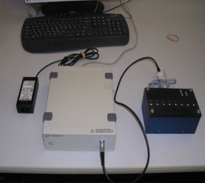
The ER818 offers a method to measure the conductivity of a liquid inside a pipette tip. This can be integrated into an automated robotic system, which delivers the pipette tip into the ET128 Octal headstage. Measuring the conductivity directly in the pipette tip has a number of advantages:
- Low sample volumes
- Low sample wastage
- Zero cross-contamination
The system has a conductivity range of 100 µS/cm to 20,000 µS/cm (the range is determined by the inner diameter of the sample tube).
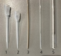
Typical sample mediums are shown in Figure 1. All are based on individual samples, except for the 1600 µm outer diameter (OD) capillary, which also allows for a continuous conductivity measurement to be made as the sample flow through the capillary.
1 Straight tube tip
2 Tapered tube tip
3 Capillary tubing with 1600 µm OD
4 Melting point disposable glass tube with 1600 µm OD
5 NMR tube with 5mm OD
The system uses a capacitively-coupled contactless conductivity measurement (C4D). This applies a high frequency signal to an excitation electrode which couples the signal to the sample. A detection electrode located some distance from the sample measures the resulting current, which is proportional to the sample conductivity. The measured quantity will depend on the physical dimensions of the test volume and its conductivity.
Equipment Required
- ER818 Octal Contactless Conductivity System, which includes:
- ER815 Contactless Conductivity Detector
- ET128 Octal headstage
- A computer with your own software to record the data (for example, Tera Term, LabVIEW, C#, WinWedge or HyperACCESS)
- Your pipette tips with samples
- A standard solution with conductivity in the middle of the measuring range, say 5 mS/cm
Experiment Procedure
A Quick Start guide describes how to connect the system, how to use Tera Term software to calibrate the system using a standard solution, adjust the gain and measure the conductivity of an unknown sample. The Quick Start guide can be downloaded from the manuals webpage.
Notes
Important Note about Temperature
The volumes of the liquids involved in these measurements are very small and subject to temperature variation. Typically there will be a 4 to 5 °C temperature difference between the ambient laboratory air and the internal temperature of the ET128 Octal headstage. This corresponds to a potential error in conductivity measurement of approximately 5-6%. Since the internal temperature of the headstage is available, temperature compensation can be performed.
Allowing some time for the temperature to equalise can also help in reducing the temperature error. Another approach is to made the conductivity measurement as quickly as possible before the sample temperature increases.
Use of a Reference Channel
In some applications where small changes in conductivity are to be measured, a reference channel is provided which operates as follows: The unknown solutions to be tested have a conductivity of say 3 mS/cm +/- 1 mS/cm. A reference solution of 3 mS/cm is selected and placed in the reference channel of the ET128 Octal headstage. Using the reference solution effectively subtracts it's conductivity value from the unknown solutions, so that only the changes are displayed. An advantage of this technique is that any temperature drift in the reference will be removed from the unknown solutions, thereby providing temperature compensation.


