PowerChrom ソフトウェアのC4D Profiler
The C4D Profiler in the PowerChrom software can be used to find the best C4D settings for your background electrolyte.
Contents
概要
このアプリケーションノートは PowerChrom ソフトウェアに帰属する C4D Profilerについて説明したものです。このソフトウェアツールは、使用するバッファー/バックグランド電解液に適した測定条件を得ることができるように考案されています。周波数、アンプリチュード及びヘッドステージゲインの各設定条件に応じて、ソフトウェアが自動的に検出器からの応答信号を記録し、一連のプロットとして表示します。このツールはC4Dシステムの機能の診断にも利用できます。
必要な装置
- ER225 C4D データシステム
- 最新バージョンの PowerChrom ソフトウェア
- C4D ヘッドステージ・プラットフォーム、 例えば ET120 C4D ヘッドステージ または ET225 Micronit プラットフォーム
- 測定方法に応じて短いキャピラリーチューブまたはマイクロ流体チップ
- 測定に用いるバックグランド電解液
- 脱イオン水
はじめに
C4D Profiler を使う前に、C4D ユニットをコンピュータに接続します。ソフトウェアが C4D ユニットを認知しないとProfiler 機能は作動しません。
キャピラリーチューブ内には、使用するバックグランド電解液で必ず充填してください。
コントロール
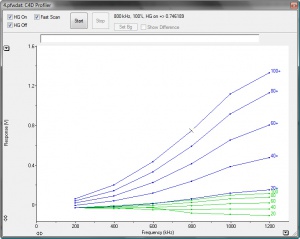
C4D Profiler は PowerChrom ソフトウェアの“Windows”メニューの中にあります。図 1. はそのコントロール、以下はその説明です:
- HG On: チェックでヘッドステージゲインはオン
- HG Off: チェックでヘッドステージゲインはオフ
- HG On と HG Off を両方選ぶと、まずヘッドステージゲイン・オフでスキャンし、次いでヘッドステージゲイン・オンで作動します。
- Fast Scan: 設定パラメータを間引いて早くテストを終了します。
- Start: テストの開始 – Stop でテストは終了します。
- Set Bg: Set Background の略で、選択するとバックグランドとしてこのランを記録します。
- Show Difference: バックグランドとして選んだランを使ってベースラインサブトラクトを実行します。新たにバックグランドを登録し次のランが表示するまで、このボタンはグレー表示となります。
手順
- C4D 装置の電源を入れ、コンピュータに接続する。
- 測定に使うバックグランド電解液をキャピラリーに充填する。キャピラリーの外側が濡れた時はキムワイプ等で拭き取る。ヘッドステージの中にキャピラリーを通す。マイクロチップ電気泳動で測定する場合は、チップのチャネルにバックグランド電解液を
充填し、ET225 プラットフォームにマイクロチップを取付ける。
- キャピラリーに溶液を充填しない状態では正常なシグナルが得られませんので注意してください。
- PowerChrom ソフトウェアを開く。
- <Manual Run> を選ぶ。
- <Start>をクリックし、ファイル名を登録する。
- Manual Sampling ウィンドウで <Stop>をクリックする。
- PowerChrom の “Windows” メニューから “C4D Profiler”を選ぶ。
- HG On と HG Off を両方チェックするとheadstage gain オンとオフの両設定をテストします。
- Fast Scan” を選べば、voltage と frequency の設定条件を一つ置きに間引き、テスト時間を1/4に短縮してスキャンします。フルのテストランでは1分程係ります。
- グラフの上に入力欄が表示します。ここにC4D装置とヘッドステージの製造番号や使用するバックグランド電解液の種類や濃度などを入力します。
- 準備が整ったら、”C4D Profiler” 画面の<Start>ボタンをクリックしテストを開始します。
- ソフトウェアは周波数に対してあるアンプリチュードの設定で生ずるシグナルを記録します。これを連続し所定のアンプリチュードで測定してグラフにプロットします。図 2. はその一例です。
- 図の右側の数字は C4D amplitude の設定値を示しています。
- 縦軸のサイズは変更できますので、プロットが重なっている場合はリサイズしてください。
- <Stop>ボタンを押せば、テスト中でも停止します。
- 縦軸のサイズは変更できますので、プロットが重なっている場合はリサイズしてください。
- HG On とHG Off の両方をチェックした場合はまず headstage gain オフ(緑線)で、次に headstage gain オン(青線) の設定で結果をプロットします。
- 前のランの測定結果は、 画面の下に通常表示するランバーのタブをクリックすれば画面に出ます。
- 上の説明のようにテストを行った結果から作動条件の指針となる設定が得られます。また下記で説明する事項にも留意し、より良好な条件が見つかるようにしてください。
- まず、headstage gain をオン(HG On) にするかオフ(HG Off) かを決めます:
- 使用するバックグランド電解液の電導度が低い場合はプロットしたシグナルは2V以下になります。この場合は HG On にします。
- 高い電導度のバックグランド電解液を使う場合は、青のプロットは全て2V以上かオーバロードします。この場合は HG Off にしてください。
- 適正な headstage gain の設定でスキャンテストを行います。
- バックグランド電解液に脱イオン水を5%程度加えて希釈し、キャピラリーに充填します。
- 希釈したバックグランド電解液を使ってスキャンテストする。
- “Set Bg” をクリックし、希釈したスキャンデータをバックグランドとして登録する。登録後の測定では、このデータがバックグランドとして使用されることになります。
- ランバー(通常は画面の下に表示)のタブをクリックし、最初のラン(未希釈のバックグランド電解液)の画面に戻し、<Show Difference> をクリックします。
- リファレンスラン(最初のラン)からバックグランドランが控除されます。伝導度に変動が生じていればそのシグナルの変化が最大限に表示しますこの電導度の変化が最大のエリアの設定条件が、最適な測定条件と見なすことができます。
- ここで用いたバックグランド電解液を使い、上で求めた C4D 設定条件に基づいて測定を始めます。クロマトグラフ画面から <Start >、<Hardware Settings>、<C4D Amplifier>を選び C4D Amplifier ウィンドウから設定条件を入力します。
- レンジの設定は 50 mV ( 電解液で生ずる僅かな電導度変化を記録するため)にしてください。測定する前に <Zero> をクリックしてオフセットをキャンセルしておきます。
Identifying the Optimum C4D Settings
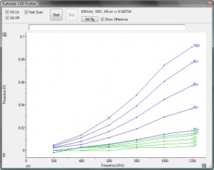
Figure 3 shows the background subtracted plots for a low conducting background electrolyte. It shows which C4D settings produced the highest output for the small change in conductivity, approximately 90mV at 100% amplitude, 1200 kHz frequency and headstage gain on.
In most experimental situations, the change of conductivity due to an analyte will be much smaller with typical signals in the 10mV range however the above test will correctly indicate the optimum C4D settings to be used.
It is generally advisable to choose parameters where the operation is still linear. In the example in Figure 3, suitable settings are 60% amplitude, 1000 kHz and with headstage gain on. In other words, find the maximum and then step back in both the frequency and amplitude to give the signal some room to move.
In some circumstances using the maximum excitation may result in the signal exceeding 2 V, at which point the detector reaches an electronic limit. In such cases a lower frequency/amplitude may be used, and in some circumstance, the headstage gain can be turned off. Cell conductivity is a proportional to the diameter and length of the measuring cell as well as the intrinsic conductivity of the buffer. This results in a very large range of conductivity values. Higher conductivities increase the current but also the frequency at which useful measurements can be made. Lower conductivities require higher excitation and higher gains.
The eDAQ headstages are configured to operate in typical capillary electrophoresis environments, but as you approach the extremes of conductivity, signals will either become too large or too small. We are prepared to modify our headstages (by special order) to adapt them to more extreme conditions.
Troubleshooting
- If you cannot see “C4D Profiler” in the PowerChrom’s “Windows” menu, then either the C4D unit is turned off, is not connected to the computer, or you are using a version of PowerChrom earlier than version 2.6.4. When no C4D device is found by the software, the C4D Profiler feature is automatically disabled.
- If you record a flat graph, with a response that stays at zero or possibly goes below zero, then your capillary is empty. You should inject your background electrolyte into the capillary.
- If you have started the scan, but don’t see any plots, try to rescale the y axis.
C4D Operation: Caution
The C4D detection method relies on the measurement of very small changes in conductivity due to analytes migrating through the detector. Unfortunately, conductivity in the detector can change for other reasons which are not always obvious. This can often causes unexpected peaks or shifts in the baseline.
NOTE: The basic C4D measurement system has negligible drift. This can be demonstrated by recording data with no capillary, or an empty capillary, in the headstage. When a change in conductivity is displayed it is can be safely assumed that it is caused by a change in conductivity of the fluid in the measurement cell.
In order to avoid or minimize these effects, the following precautions should be taken:
Temperature effects: Temperature directly affects conductivity and the changes which occur can have similar amplitudes as the peaks of interest. However temperature changes often show up as a slow step change or as a baseline drift. The C4D system itself exhibits negligible baseline drift. It is advisable therefore to allow the head stage and the capillary to stabilize at its operating temperature. This takes 20 to 30 minutes.
Pressure effects: applying hydrostatic pressure to the fluid in the capillary will cause transient baseline shifts due to subtle changes in conductivity caused by flow and associated temperature changes in the moving fluid. During measurements, time should be allowed for loading effects to stabilize.
Fluid discontinuities: Bubbles can come in different sizes and will cause excursions in conductivity. These can mimic actual analyte peaks but will, in all cases, cause a decrease in conductivity (negative peaks).
Mechanical effects: Moving the head stage or the capillary will inevitably vary the coupling between the capillary and the headstage and cause a baseline shift. External vibrations can also be coupled into the signal. It is advisable that the headstage be firmly connected to a stable mechanical support.
Electrical effects: The coupling between the headstage and the CE is dependent on very small values of capacitance whose value can be altered by external objects. For example, changing the position of the headstage can alter the baseline. External electrical noise can also couple through the headstage cable and it should always be rolled up into a minimum size and be constrained so that it does not move.
In conclusion, in order to obtain stable and repeatable results, ensure that the headstage, its connecting cables and the capillary are held firmly in place in a stable temperature, mechanical and electrical environment.


