Signal Sources and Amplifiers
Introduction
In order to record an experimental signal with high fidelity 3 issues need to be considered.
- Signal Sources to be measured
- Characteristics of the signal sources
- Type of Amplifier used to record the signal
Signal Sources
There are 4 types or classes of electical signal sources which occur in various experimental situations. It is important to understand the characteristcs of these signal sources in order that they can be matched to the correct amplifier/recording system without degrading the accuracy of the measurement.
NOTE: In discussing the characteristics of signal sources reference will be made to "Source Impedance" which in its most general form consists of a combination of 3 electrical elements: Resistance,Inductance and Capacitance. In most cases one of these elements will predominate, most commonly resistance. So when the term "Source Resistance" is used it implies that the impedance of the source is mainly resistive in nature. At DC or low frequencies source impedance is mainly resistive. The other elements, capacitance and inductance only come into play at higher frequencies.
http://en.wikipedia.org/wiki/Electrical_impedance
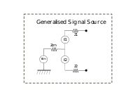
In its most general form a signal source can be described by the following diagram:
The 4 classes are listed and discussed below:
Single ended-Floating
Single Ended Floating signals appears between the two terminals of the signal source. Either of these terminal can be grounded without altering the potential across the two terminals. All signal sources can be regarded as Voltage or Current sources as defined in Nortons Theorem.
http://en.wikipedia.org/wiki/Norton%27s_theorem.
In an analytical laboratory:
Typical voltage ranges: 1uV (thermocouples)to 30,000Volts (capillary electrophoresis high voltage supplies) - internal impedances are typically low. Typical current ranges: <1pA (small amperometric electrode) >10Amps (high power potentiostat) - internal impedances are Typically high. Signal frequency content: DC to MHz
An ideal voltage Source has a near zero internal impedance. An accurate reading can only be obtained with a measuring circuit whose own internal resistance is much higher than the source resistance of the source. Voltmeters therefore need to have a high internal reistance - ideally infinite.
An ideal current Source has a near infinite internal impedance. In this case to measure the source current the measurement impedance should be very low. Ammeters therefore need to have a low internal resistance - ideally zero.
Examples SE Voltage sources
- Battery - very low internal resistance
- pH cell - very high internal resistance
- Thermocouple - very low internal resistance
SE Current sources
- Silicon detector - high internal reisitance
- Electrochemical sensor - high internal resistance
- Piezo-Electric sensor - very high resistance
Single ended - Grounded with Common mode voltage
In this configuration one of the terminals is effectively connected to ground via another signal source - called a "Common Mode Voltage". This CM Voltage may be intentional but in most cases it is unintentional and can present a significant problem in the measurement of the signal of interest. In this case the effective signal occurs across the two terminals of the source and is made up of the signal with the CM voltage added to it as shown below. A special but common case of this configuration is when the CM voltage is zero and one of the terminals is effectively connected to ground.
Add picture of single ended with common mode voltage.
Examples of Single Ended Grounded with common mode
- AC Line powered signal generator
- Resistive shunt for measuring current
- AC powered transducer
- Chromatography detector
Balanced - Floating
In this configuration the two terminals are both active and have equal impedance to a common point which is floating and unconnected to ground. The voltage on the two terminals moves in different directions in relation to the common point.
Add picture of single ended with common mode voltage.
Examples of Balanced floating Source
- Four Arm Wheatstone Bridge with floating power supply
- Linear variable differential transformer (LVDT)
- Center tapped Transformer
Balanced - Grounded with Common mode voltage
In this configuration the two terminals are both active and have equal impedance to a common point which is connected to ground via a CM voltage. The voltage on the two terminals moves in different directions in relation to the common point. The CM votage can either be Zero when the center point is directly grounded, it can be at a fixed DC value or can result from unintentional connection to ground.
Add picture of single ended with common mode voltage.
Examples of Balanced floating Source with coomon mode voltage
- Four Arm Wheatstone Bridge with line powered supply
- Differential output Operational Amplifier
Source Characteristics
Characteristics of electrical signal sources in a Chemistry analytical laboratory.
Examples:
Single Ended Referenced to Ground
In this case one terminal contains the signal and the other terminal is referenced to ground. This reference to ground can be modelled by an Impedance and a series voltage source. These are referred to as Common Mode Impedance Zcm and Common Mode voltage Vcm
There are three distinct conditions: Zcm is infinite: The signal source becomes a “Floating source”. Examples: pH electrode pH/Ion selective electrode piezo electric sensor Thermocouple Battery or battery powered instrument or meter
Zcm is zero: The signal source becomes “Grounded source”. One terminal carries the signal and the other is connected to ground or 0 volts. Examples: AC powered instrument like a signal generator
Zcm is nonzero: This represents most practical situations. This term is sometimes introduced as a necessary component in the measurement system but typically it represents a “noise” element to be avoided by the choice of an appropriate amplifier input configuration.
AC powered equipment
Source Impedance
The signal source impedance will determine the type of Amplifier required to measure the signal.
Source Voltage
The source voltage will determine the amplification level required in the recorder amplifier
Source Frequency content
The source frequency content will determine the frequency response of the recorder amplifier.
Amplifier types
The amplifier input configuration required will be determined by the Source configuration discussed above.
